© PanelSat GmbH
| Home | History | SoSo-steering | MSU | DTU | Operation | Contact |
|
Gravitational Attitude Control and Inertia Transfer (via MSUs) Orphée et al. describe in their paper the NASA NEA Scout spacecraft, which autonomously manages its momentum by shifting the center of mass (CoM) using a newly developed AMT (Active Mass Transfer) unit. PanelSat adopts a similar principle but implements it with a distinct structural and functional design. PanelSat’s Mass Shifting Units (MSUs) are mounted in opposing pairs at the spacecraft’s rim. Each MSU moves an internal mass vertically, relative to the spacecraft’s structural plane. Unlike thrust-based systems, these movements aim to redistribute mass intentionally, allowing the spacecraft to react to external gravitational forces without expelling any propellant. The key idea behind this concept is balancing: By adjusting the internal mass distribution with respect to a vertical reference – real or virtual – the system is expected to reach a self-stabilizing state where gravitational torques are minimized or cancelled. This would result in a passive, gravity-guided orientation of the spacecraft. As a reference, the system uses: a real thread, in ground-based testbeds where the satellite is suspended, or a virtual gravity line, inferred from onboard inertial sensors during free-flight. While this principle is mechanically implemented and theoretically sound, it has not yet been experimentally validated in microgravity. A proposal has been submitted to ESA to investigate this “virtual thread” control principle aboard the ISS. The goal is to confirm whether gravitationally guided balancing via internal mass shifting can provide a reliable and propellant-free method of spacecraft attitude control – or whether the concept requires revision. If successful, this would greatly simplify the design, simulation, and testing of PanelSat-based spacecraft: The virtual thread would serve as a universal alignment reference, allowing engineers to test attitude behavior under gravitational influence (by using a real thread on a suspended model) without complex sensor networks or ground-based analogues. This would enable low-cost validation scenarios, straightforward microgravity demonstrations, and ultimately more accessible pathways for early mission development and qualification. Inertia TransferMSUs allow also Inertia transfer via mass motion. It is governed by conservation of angular momentum. When masses accelerate along a radial axis or a circular track inside the satellite structure, they apply torque to the supporting frame. By synchronizing opposing mass movements (e.g. MSU1 upward, MSU2 downward), rotational acceleration of the satellite body is induced, analogous to a reaction wheel system but without rotating parts. |
|
PanelSat's MSU concept is not limited to internal sliding masses.
Any controlled movement of mass relative to the spacecraft body can contribute
to attitude reorientation when the system is in microgravity or suspended from
a low-friction support. Robotic arms, docking arms, movable sensor heads or
other controlled appendages can therefore be considered as additional
mass-shifting elements.
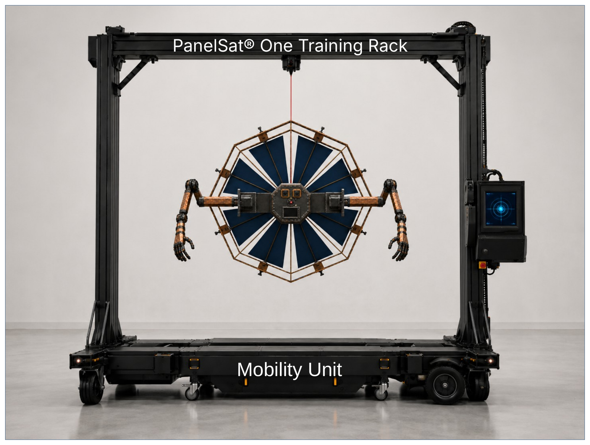
A useful public demonstration is the microgravity video of ISS Commander Takuya Onishi showing how circular leg movements can rotate the human body without pushing against a wall. The same conservation-of-angular-momentum principle also applies to arm movements. The video makes the principle very clear: a non-rigid body can deliberately change its attitude by moving its own limbs in a controlled sequence. Such movement does not provide propulsive translation; it changes the attitude or orientation of the body. Reference video: Takuya Onishi demonstrates conservation of angular momentum in microgravity. This principle is directly relevant to the PanelSat Robotic Module. PanelSat One has no legs, but it can use robotic arms and a third docking and alignment arm. In the ground demonstrator, this third arm is mounted below the suspended body. If the motor axis of this arm is aligned with the real suspension thread, a controlled rotation of the docking and alignment arm should create a clearly measurable and controllable counter-rotation of the PanelSat body. With suitable motor resolution, sensor feedback and calibration, it is very likely that this configuration can enable precise attitude rotation around the suspension axis. In free flight, the same geometry can be treated as a virtual reference axis derived from onboard inertial sensors. A rotating or folding arm would then act as a visible reaction-mass appendage. By commanding defined arm motions and measuring the resulting body response, PanelSat One could use its robotic arms not only for manipulation and docking, but also as part of its attitude-control system. The effect must be understood as attitude control, not as orbital propulsion. In a closed system, internal mass motion cannot move the overall center of mass onto a new orbit. However, it can reorient the spacecraft, and once the vehicle has been reoriented, external torques such as solar radiation pressure can be used to maintain, amplify or modify the rotational state. This opens an additional development path for PanelSat: MSUs, robotic arms and docking arms can be combined as complementary attitude-control elements. MSUs provide compact internal mass motion; robotic arms provide larger visible reaction masses; and solar radiation pressure provides the external torque field needed for sustained propellant-free control. PanelSat One Training RackThe image shows a concept view of PanelSat One suspended by a central thread inside a mobile training rack. In this version, only the two main manipulator arms are shown. A third docking and alignment arm, mounted below the body, is planned as a further development. The purpose of this training setup is to make the effects of controlled mass shifting visible already on Earth. When the suspended model changes its internal mass distribution or moves its robotic arms, the resulting reaction of the body can be observed around the real suspension axis. Such a ground-based thread model cannot fully reproduce free flight in space, but it can serve as a practical and low-cost test environment for first demonstrations of mass-shift-induced attitude changes. A combined test campaign using both a thread-suspended Earth model and a freely floating ISS model could help validate whether the observed mass-shifting effects are only artifacts of the suspension system or whether they represent a transferable attitude-control principle for free-floating spacecraft. This approach is especially relevant for PanelSat One, because robotic arms, movable docking mechanisms, and internal mass-shifting units can all act as controllable masses. Together with external torques such as solar radiation pressure, these mechanisms could support propellant-free attitude control and controlled reorientation of future PanelSat-based spacecraft and space based construction and service robots. Just again, take a look onto Takuya Onishis ISS-Mikro gravity demonstration, how he moves his legs. A third turnable docking arm under Ones thread line would allow to turn the robot about its thread axis. Reference video: Takuya Onishi demonstrates conservation of angular momentum in microgravity.
|
| Home | History | SoSo-steering | MSU | DTU | Operation | Contact |